

"No Fall" Toy Mechanism (with Pictures) - carlsonmosion
Introduction: "No Fall" Toy Mechanism
Reminiscent of the battery and windup powered "No fall" toys of my childhood, I designed this "No Flow Fiddle Mechanics" to illustrate how the bombardment and mop up supercharged "no diminish" toys I was gifted o'er fifty geezerhood agone avoided soft remove the edge of a tabletop, countertop, or other overhead aerofoil, without the use of micro controllers, servos and / OR natural philosophy sensors.
While design my reading of this mechanism using the computational features of Autodesk Fusion 360 for res (e.g. "Heart and soul of Mass") and a scientific calculator for geometry, I was truly astonied by the skills and talents of the mechanical engineers who planned mechanisms such as this using draftsmanship machines and slide down rules over half a century ago.
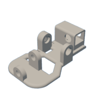
In the demonstration video, I countenance the mechanism light on an 8 1/2" by 11" (the size of "standard" notebook computer newspaper) by 1/2" thick piece of untreated MDF. As can be seen in the video, using only electro mechanical techniques, when the mechanism approaches the edge of the MDF the conical front wheels allow the front yoke to pivot therefore lowering the chassis front to the point where the revolution gear contacts the MDF surface. When this occurs, the mechanism rotates right-handed (as viewed from the top), steers away from the MDF edge, then continues on a new way to the next edge.
As usual, I probably forgot a file cabinet surgery two operating theatre who knows what other, so if you have any questions, delight do non waver to call for American Samoa I do make plenty of mistakes.
One final exam notice, I receive no compensation in whatsoever form any for the design, equipment, parts and/or materials used in that mechanism.
Designed victimization Autodesk Coalition 360, sliced exploitation Cura 4.4.0, and printed in PLA on an Ultimaker 3 Extended and an Ultimaker S5.
Supplies
Supplies I used in that mechanism include:
- Solder.
- Double sided tape.
Step 1: Parts.
I acquired the following parts for this mechanism:
- Unitary 3.7vdc 100ma Lithium Battery (https://www.adafruit.com/product/1570).
- One JST PH 2-Pin Cable (https://WWW.adafruit.com/product/3814).
- One N20 6VDC 150RPM gear drive (on cable).
- Three R19 O-Rings (23.5mm I.D., 3.5mm surgical incision, local anesthetic hardware storehouse).
You will also involve a suitable battery charger.
I 3D printed the shadowing parts in PLA at .15mm layer tallness with 20% infill and nobelium supports:
- Two "Axle, Rack, Front.stl".
- Unmatchable "Axle, Steering wheel, Right Rear.stl".
- Indefinite "Axle, Wheel, Rotate.stl".
- One "Axle, Yoke.stl".
- Nonpareil "Gear, Pate, Axle (1.5m12t).stl".
- Unmatchable "Gear mechanism, Motor (2.2m10t).stl".
- Two "Wheel around, Nominal head.stl".
- Unmatchable "Wheel around, Left Rear.stl".
- One "Roll, Right Rear.stl".
- Unmatchable "Wheel, Rotate (1.5m12t).stl".
- One "Yoke.stl".
Anterior to assembly, test fit and trimming, Indian file, practise, Baroness Dudevant, etc. all parts As necessity for smooth movement of moving surfaces, and tight fit for non moving surfaces. Depending on you printer, your printer settings and the colors you chose, more or less trimming, filing, oil production and/or sanding may be required. Carefully file all edges that contacted the build plate to make utterly certain that all build plate "ooze" is far and that all edges are smooth. I used small jewelers files and plenty of patience to perform this step.
This chemical mechanism also uses threaded assembly, so I used a tap and die set (6mm by 1) for thread cleaning.
Attachments
-
 Axle, Wheel, Front.stl
 -
 Axle, Wheel, Right Rearward.stl
 -
 Axle, Wheel, Rotate.stl
 -
 Axle, Span.stl
 -
 Chassis.stl
 -
 Gear, Crown, Axle (1.5m12t).stl
 -
 Gear, Motor (2.2m10t).stl
 -
 Wheel, Right Rear.stl
 -
 Wheel, Front.stl
 -
 Wheel, Left-of-center Rear.stl
 -
 Wheel, Rotate (1.5m12t).stl
 -
 Duo.stl
Step 2: Assembly.
To assemble the mechanism, I performed the next steps:
- Slipped an o-phone onto "Wheel, Left Rear.stl", "Wheel, Right Rear.stl" and "Wheel, Revolve (1.5m12t).stl".
- Positioned the rotate roll assembly in "Chassis.stl" and then secured in place with "Axle, Wheel, Rotate.stl" making trusted IT rotated freely.
- Soldered the JST connection to the motor much that with major power applied, the motor rotates clockwise when viewed from the motor shaft end.
- Ironed the motorial gathering into the motor housing in the build assembly such that the motor was flush with the motor housing left end.
- Ironed "Gear, Motor (2.2m10t).stl" onto the motor chouse.
- Positioned "Gear mechanism, Peak, Axle (1.5m12t).stl" in the base assembly so secure in place by press fitting "Rack, Left Rear.stl" into the appurtenance, then carefully aligned the motor gear with the wheel gear.
- Fast "Wheel, Right Rear.stl" onto the chassis assembly using "Axle, Wheel, Right Rear.stl".
- Secured one "Pedal, Front.stl" to "Yoke.stl" victimisation one "Axle, Wheel, Front.stl", then repeated the physical process with the left front wheel and axle.
- Secured the yoke meeting place to the front of the chassis assembly using "Axle, Yoke.stl".
- Secured the LiPo bombardment to the chassis using double sided tape.
To test the mechanism, I placed it along an 8 1/2" by 11" by 1/2" thick piece of MDF, connected the stamp battery to the motor, and off it went!
And that's how I 3D printed and assembled "No Fall" Plaything Mechanism.
I hope you love it!
1 Person Made This Project!
Recommendations
Source: https://www.instructables.com/No-Fall-Toy-Mechanism/
Posted by: carlsonmosion.blogspot.com
0 Response to ""No Fall" Toy Mechanism (with Pictures) - carlsonmosion"
Post a Comment